Gilisymo LS53L0X and Arduino Due
This article will show you how to
connect the brand new Gilisymo plugin the LS53L0X to an Arduino Due.

What is Gilisymo plugin?
Gilisymo is a French company based
in Grenoble, created on 2017.
The first product from Gilisymo is
an intelligent distance sensor the LS53L0X based on two
STMicroelectronics's components: a time of flight and a stm32f030
microprocessor. It is used on Robotics, Automations, Gesture and more.
 The LS53L0X plugin is capable to provide a distance from 3
cm to 200 cm.
The LS53L0X plugin is capable to provide a distance from 3
cm to 200 cm.
The difference with other distance
sensors is the internal FW of the stm32f030 and the fact
that when we give the power to the LS (used to simplify LS53L0X)
it provides the ranging distance on the three interfaces UART, i2c and PWM.
In addition, there are lot of
control parameters to customize the quality of the ranging to modify the
interrupt signal or to customize the PWM signal.
Let start and see how it is simple
to use LS!
The connection
The LS needs only four wire for this
tests, +3v3, GND, TX and RX, connected as follow.

The sketch
The first example will show how to send
basic commands over UART. The sketch send "disable" command to the LS
then wait 5 second, then send "enable" command and again wait for 5
second.
The visual effect in the serial monitor is
that we have data for 5 seconds and nothing for next 5 seconds, then this
repeat indefinitely.
You can find the Source code on the following link:
The first
example is the SerialEnableDisable_ls53l0x.
Setup and UART config

Here we use two serial ports from Arduino Due: Serial and Serial1.The Setup() function will initiate both Serial and Serial1 to 115200 baud.The Loop() starts with the Serial/Serial1 connection.Both Serial and Serial1 are connected together and in that case, we can use the Serial1 for the LS plugin and the Serial for the output in the serial Monitor

The second part of the Loop() uses a switch case to avoid using delay function that is blocking. In fact, in that case, the connection between the two serial ports cannot be functional; the risk is to loose data.
The first command sent to Serial1 is the “disable”.
Serial1.println("disable");
The timer is stored in Timer variable and in the next
loop the switch case is on case 1.
In the case 1 a check is done to know if 5 seconds has
done. In that case in the next loop the switch case in on case 2.
In case 2 the new command is sent to LS plugin:
Serial1.println("enable");
The timer is stored in Timer variable and in the next
loop the switch case is on case 3 (default).
In the case “default”, a check is done to know if 5
seconds has done. In that case in the next loop the switch case restart from
case 0.
At
the end we can see 5 second ranging followed by 5 seconds not ranging. This sequence
repeats indefinitely.The output of serial monitor

Example with serial plotter
Instead of
using the serial monitor, we can use the serial plotter. New version of serial
plotter accept to have text and number so even if the LS output the prompt, the
plotter ignore it.
For this example,
I will use the SerialEnableDisable_ls53l0x example that you can find in the
same GitHub:
The
differences between the first example and the new one are on the setup
function.
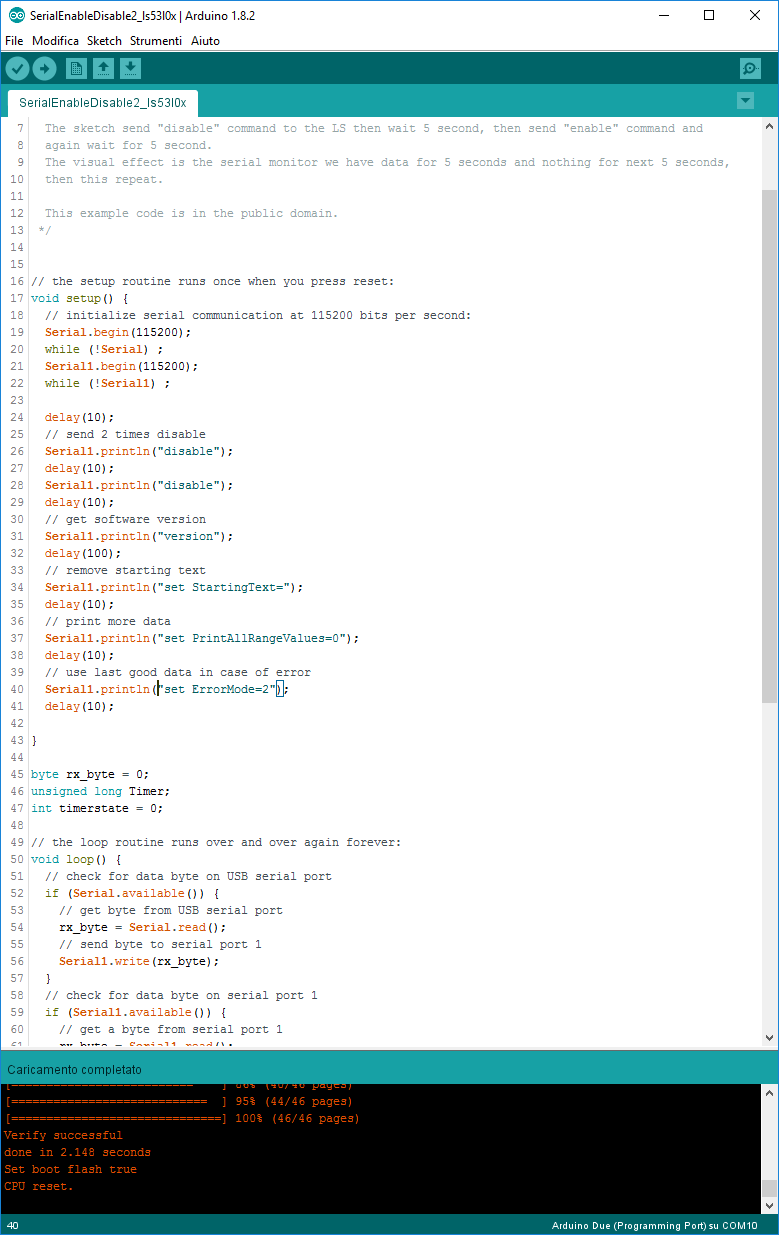
In the
Setup code we do two times disable, this to be sure to send the command.
Normally we
should send command and wait for the prompt, if the prompt does not arrive then
send command again and repeat this until a timeout, in the example we simplified
by sending commands two times.
We print
the version of the LS FW with the following:
Serial1.println("version");
The output
is:
LS53L0X>
LS53L0X V1.6.129
We change
the starting text with the command:
Serial1.println("set StartingText=");
After this command,
the starting text is empty and we have only numbers.

The
following command will ensure that only ranging value is printed and not all the
internal values from VL53L0X:
Serial1.println("set
PrintAllRangeValues=0");
The
following command will force to use the last good ranging data in case of
error:
Serial1.println("set ErrorMode=2");
Now I run
the plot instead of the monitor:

You can use
more commands to customize the LS plugin, you can find them in the LS
documentation:
Comments
Post a Comment